

Valuable information about charging the RV’s house battery bank, troubleshooting, and more.
By Gary Bunzer, Technical Editor
April 2020
The March 2020 issue of Family RVing included the first installment of a two-part article about the RV 12-volt-direct-current (DC) system. It focused on battery discharge and charge cycles, battery banks, and battery testing. This month’s installment begins with a discussion of battery charging.
But first, another reminder: If you choose to follow any instructions outlined in these articles, first satisfy yourself that neither personal nor product safety will be jeopardized. If you are in doubt or do not feel comfortable about a procedure, do not continue. Make an appointment with an RV service facility.
Proper battery charging and discharging are the keys to optimum performance and long battery life. All charging devices should be designed to take into account the size of the battery bank and the type of batteries.
RVers have several options for keeping the house battery bank charged. They include:
- Converter/charger
- Inverter/charger
- Portable battery charger
- Engine alternator
- Photovoltaics (solar charging)
Note: The RV generator is not included, because typically it is not configured with a battery charging circuit. The RV generator simply provides 120-volt-AC (alternating current) output that powers other methods of charging the battery bank.
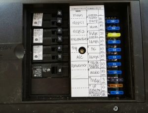
This converter was built into a distribution panel with 120-volt-AC circuit breakers on one side and 12-volt-DC fuses on the other.
Converter/Charger
A power converter adds a voltage source for the RV’s 12-volt-DC loads. The device’s main function is to convert incoming 120 volts AC to 12 volts DC, thus energizing 12-volt devices such as fans, lamps, motors, and pumps. When possible, it is wise to plug the shoreline cord into a verified source of 120 volts AC. Using the converter conserves the amp-hours stored in the battery bank.
Although not all converter/chargers are created equal, most provide some amount of battery charging current while powering all the DC loads in the RV. The RV converter is not simply a 12-volt power supply. The battery, wired in parallel with the converter, acts as a filter to smooth out the typically ragged output of some converters. In fact, some converters will not function at the proper voltage unless the battery bank remains in the system.
Converters are fully automatic and rated by the maximum number of amps they can provide. Simply plug into shore power (or start the generator) and the converter becomes energized. Converters may be configured differently and use different technologies, but their basic function remains the same. Some converters are built into a distribution panel that features 120-volt-AC circuit breakers on one side, and the low-voltage, 12-volt-DC fuses on the other side. It can be thought of as an electrical control center. The converter is located at the busy intersection of the 12-volt-DC system and the 120-volt-AC system.
RV converters often are incorrectly blamed for electrical problems. According to some surveys, as many as 90 percent of converters returned as defective were in fact fault-free. But some converters do fall short in effectively charging batteries. Seldom does a battery bank ever approach the 75 percent to 85 percent charged level from a basic converter/charger, and a fully charged battery bank is rare.
Some RV charging converters — those that I consider to be mediocre — have been designed to achieve, at best, a compromise between overcharging and undercharging a battery bank, simply because the converter manufacturer did not know the type or number of RV batteries. As a result, many battery banks never attain full capacity during the charging cycle, nor are they ever fully protected from overcharging. That minimizes and, in some cases, drastically shortens battery life.
Since the converter provides a 12-volt-DC output, as does the battery bank, and they are connected in parallel, a method of switching must be employed to differentiate between the two. Most converters accomplish this with automatic relays. In modern “smart” converter/chargers, the incoming 120 volts AC is converted to 120 volts DC and is reduced through a much smaller and lighter high-frequency transformer to the lower voltage. The pulsed output of the high-frequency transformer is further rectified to produce an extremely clean and smooth current flow into the batteries.
Among converter/chargers, the multistage type is by far the most advantageous. Sophisticated multistage charging converters include, or offer as an option, a monitor for measuring battery voltage and current flow to and from the battery bank. These converters employ state-of-the-art charging criteria developed specifically for deep-cycle batteries, and they take into account the battery temperature, the total amp-hour capacity of the battery bank, and the type of battery. A user interface allows the RVer to choose the size of the bank and the type of battery. Four charging sequences are incorporated into sophisticated converter/chargers: boost, absorption, float, and equalization.
In a depleted battery bank, the typical multistage charge sequence first applies a boost charge that basically places all the converter’s available amp-hour output into the depleted battery bank until the voltage approaches the gassing point (around 14.2 to 14.4 volts). The boost stage brings the battery up to about 75 percent to 80 percent full in the shortest amount of time. Although the charging current is slowly reduced as the voltage increases, this is considered a constant current stage.
The absorption stage is sometimes referred to as an acceptance charge. The batteries are charged at a constant voltage of about 14.4 volts DC as the current flow to the battery bank slowly decreases to about 1 amp for every 100 amp-hour capacity of the total bank. The voltage decreases as the battery temperature rises. At that point, the battery bank is considered fully charged.
After the current has been reduced during the absorption stage, batteries enter a maintenance-type charge sequence called the float stage. The float charge offsets the inherent self-discharge common to all chemical batteries. A constant voltage of about 13.3 to 13.5 volts is applied at a low amperage of about 0.1 to 0.3 amps for every 100-amp bank capacity (some chargers deliver a flat float current of 1/500 to 1/1,000 of the total battery capacity). This is the point at which many mediocre converter/chargers begin to boil the electrolyte when left connected to shore power for extended periods. The design of a “smart” converter eliminates this.
Equalization, available on some smart converter/chargers, is a controlled, intentional overcharge designed to minimize or prevent sulfation and electrolyte stratification in flooded batteries and some absorbed glass mat (AGM) batteries. During normal charge cycles, especially in hotter climates, high temperatures and impurities in the electrolyte may prevent some cells from attaining a full charge, while allowing more sulfation on the plates. Most, if not all, battery makers recommend a periodic equalization charge to maximize the potential of flooded batteries. I contend not many professional RV service techs are even aware of this fact.
Inverter/Charger
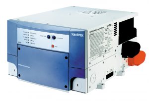
An inverter/charger can be an effective battery charger.
Many sophisticated DC-to-AC inverters incorporate an effective, high-output “smart” battery charger — they are inverter/chargers. When plugged into shore power or when the generator is running, the inverter employs the same charging algorithms as a smart converter/charger.
A power inverter/charger is the electrical opposite of a converter/charger. That is, DC output from the battery bank is inverted to 120-volts-AC output. Electronically processed, this inversion is totally silent. There are no moving parts aside from an occasional cooling fan feature.
Inverters designed for RVs are available in two output waveform technologies: quasi-sine wave (also called modified sine wave or square wave), produced by low-frequency transformers; and pure sine wave (also called true sine wave), produced by microprocessor-controlled, high-frequency circuits and components. Low-frequency inverters are less expensive, and sometimes efficient, but they are prone to voltage fluctuations that can cause disturbances in some AC circuits or components. Pure sine wave inverters, on the other hand, are extremely sophisticated and can produce AC power at or above the quality of shoreline power grids. The bottom line is that modern, pure sine wave inverter/chargers make very effective battery chargers.
Portable Battery Charger
The advantage of this device is that it can be connected to either of the 12-volt battery systems — the house battery bank or the chassis battery bank. Usually that’s not the case with the sophisticated charging converter; most are configured to the house battery bank only, though there are a few exceptions.
Having a small portable charger on board makes it possible to charge the house battery bank and the chassis batteries when you’re connected to shore power; running the generator; or using the quieter form of 120 volts AC, the inverter.
Engine Alternator
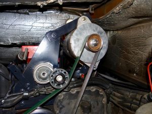
A chassis engine alternator.
A motorhome chassis’ engine alternator charges both the chassis battery bank and the house battery bank. The stock alternator could be undersized for the loads in the coach, especially if the owner adds more 12-volt-DC loads; the same can be said for the alternator in a truck that tows a travel trailer or fifth-wheel. A high-performance alternator can upgrade the DC system. Often, installing such an alternator involves a simple bolt-for-bolt replacement using common hand tools.
Remember that the chassis battery bank and the house battery bank always must be totally separated, regardless of the number of batteries in each. Each contains a vastly different type of battery designed specifically for each system. Combining the two technologies shortens battery life.
You should know the type of battery separation device your RV has — diode-based battery isolator or solenoid. It is equally important that the device be electrically correct and sized properly to protect all batteries.
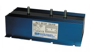
An RV’s battery separation device may be a diode-based battery isolator.
Diode-based battery isolator: A multibattery isolator is a solid-state device composed of diodes that distribute current from the chassis alternator to the chassis battery bank and to the house battery bank independently.
The rated capacity of the isolator must exceed the rated output capacity of the chassis alternator. Undersized isolators quickly burn the diodes when exposed to high output from the alternator. The isolator splits the alternator’s output, with half the charging amperage going to the chassis battery and the other half going to the house battery bank. It’s not the best separation method, because a voltage drop occurs across the diodes. Thankfully, most motorhome manufacturers have moved away from diode-type isolators in favor of a solenoid.
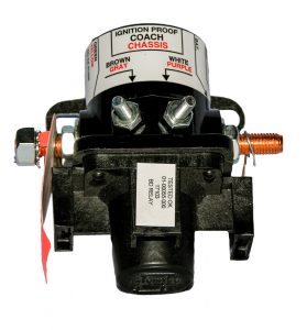
An RV’s battery separation device also may be a solenoid.
Solenoid: This device incorporates a high-capacity, electronically controlled solenoid switching relay within a well-monitored charging system. Solenoids begin charging the house battery bank only after the chassis battery has regained a certain threshold (around 13.2 volts DC) after the engine starts. Until then, the battery systems are kept separate. This is a significant upgrade over the older, simplified, electromechanical solenoid.
Photovoltaics/Solar Charging
Many manufacturers prewire RVs for solar packages, similar to the air conditioner or generator prewiring of years past. Others are installing solar panels and complete systems at the factory.
The charge controller is the most important component in an RV solar charging system. Regardless of the type, size, and number of solar panels, the charge controller, much like the sophisticated inverter or converter/charger, must deliver the correct amount of amperage, pushed by the right amount of voltage, while taking into consideration the temperature of the electrolyte in the batteries.
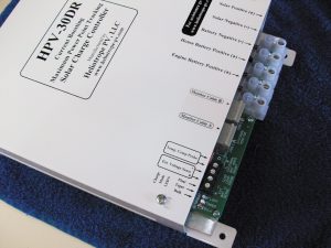
A charge controller is the heart of an RV solar-charging system.
In some inexpensive prepackaged systems, the charge controller may be listed as an optional voltage regulator. In reality, it is a must-have item that protects the battery bank from overcharging. If you envision using solar energy to augment your battery-charging capability when dry camping, insist on a voltage regulator, if not a sophisticated charge controller. A good rule of thumb: If the peak charging current of the solar array is greater than 1.5 percent of the total battery amp-hour capacity, insist on a quality charge controller.
A multistage pulse-width modulation (PWM) charge controller is the most sophisticated and most highly recommended type. PWM is a complex method of battery charging that always maintains the battery bank at its highest state of charge. PWM charge controllers pulse on and off thousands of times per second. The “off” pulse lasts a little longer as the battery voltage rises. This type of controller employs a metal-oxide-semiconductor field-effect transistor (MOSFET), which prohibits nighttime reverse-flow battery discharges commonly associated with less sophisticated, inexpensive controllers. PWM controllers also feature maximum power point tracking; reverse polarity protection; over-temperature protection; and an LCD digital display for battery voltage, output charging current, and optional tracking of current being consumed by RV systems.
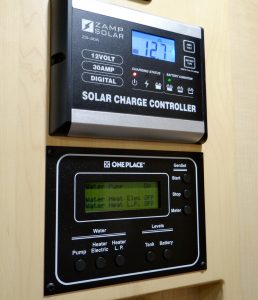
The digital display of a solar charge controller.
Some controllers incorporate full-time 30-amp charging capability, including temperature compensation (extremely important) and automatic battery equalization. The equalization charge (as noted previously, required only for flooded, lead-acid, and some AGM battery banks) provides a very slight overcharge at regular intervals (30 minutes every 24 hours). This helps prevent battery plate sulfation and electrolyte stratification, and allows all battery cells to reach full charge.
Advanced charge controllers employ user-defined parameters for battery amp-hour rating and battery type. Typically, top-of-the-line solar charge controllers have four charging stages similar to those found in the sophisticated inverter and converter chargers previously mentioned. Some charge controllers are even equipped with an additional battery-charge circuit for the chassis battery bank. This is a nice feature for motorhome owners. In some cases, an inverter/charger and converter/charger also may provide a separate charging circuit for the chassis battery.
Conductors And Overcurrent Protection
All wiring in an RV’s DC system should be stranded conductors (that is, each conductor is made from multiple thin wires). With the exception of thermostat wiring, solid copper wire is not permitted in low-voltage applications. This is important to remember should an RV owner install additional 12-volt-DC components. All wiring should be listed by an agency such as UL or CSA. The listing agency is inked onto the wire insulation.
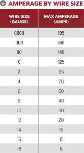
The conductors should be sized appropriately and in accordance with the load and the overcurrent protection. Fuses and circuit breakers protect not only the installed device but also the conductors. It is okay to use a fuse or a circuit breaker sized smaller than the recommended conductor requires. But never use a fuse or breaker sized larger. The accompanying chart shows the maximum amperage for each wire size commonly used in RVs.
 A protection device does its job by opening or blowing when the amp draw exceeds the protection device’s rating. This could be the result of a short; too many devices on the same circuit drawing power at the same time; or excessive current drawn by a load, such as when a slideout motor sticks or binds. Some 12-volt circuit breakers automatically reset, but a blown fuse, obviously, must be replaced. Look at the low-voltage circuits in your RV and determine the sizes of fuses and circuit breakers needed. Be sure to carry spares. Again, never substitute a fuse or breaker rated higher than that allowed by an individual circuit. When installing new low-voltage equipment, always place the circuit protection device as close to the power supply as possible.
Low-Voltage Connectors
Solderless connectors used in 12-volt-DC wiring come in a variety of sizes and shapes. Many RV owners are familiar with the ring terminal, spade terminal, butt splice, etc. It is important to use the correct size connector for the gauge of wire being installed. Large conductors simply will not fit into a connector that is too small; never trim away copper strands just to make it fit. A connector that is too large will not crimp and grab onto the strands properly.
Be sure to use a high-quality crimping tool. Cheap tools may not properly crimp the connector onto the wire, raising the risk it eventually will loosen. In fact, I recommend going one step further by applying heat-shrink tubing over the connector and a portion of the insulation on the conductor. In addition to providing a secure connection, the tubing protects against moisture intrusion and corrosion buildup.
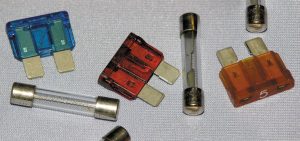
When traveling, RVers should always carry spare fuses and circuit breakers.
Troubleshooting Tips
Most 12-volt-DC operational problems fall into one of two categories: battery current loss (battery drain) and open circuits. When troubleshooting, consider the following:
- The system in general
- The circuit in that system
- The component in that circuit
First, determine whether the problem is with the chassis system or the house system. Next, analyze which circuit in that system is affected. And, finally, pinpoint the component in the circuit that may be the cause. Use the process of elimination. Work from big to little, general to specific. Here are a couple of examples:
Battery current loss/drain: Let’s say the house battery bank keeps going dead, and it’s evident the problem lies somewhere in the RV portion, since interior components are exhibiting problems. You can check for a drain on the house battery circuits not rated above 10 amps by setting a digital multimeter (DMM) to the 10-amp scale (or larger).
First, turn off all 12-volt devices and unplug the shore cord. If a solar charging system is on the roof, ensure the charge controller is turned off. Disconnect the frame-grounded negative cable from the battery bank. The battery system is now in an open-DC-circuit condition. Connect the red test lead from the DMM to the cable you just disconnected, and connect the black test lead to the negative terminal on the battery bank. The DMM, inserted in series with the negative cable, now completes the circuit. Immediately, the DMM should indicate how many amps are being drained. The meter will indicate the drainage in amps or possibly milliamps (mA).
Next, double-check that all 12-volt appliances, lamps, etc., are turned off; don’t forget lamps inside wardrobe closets or storage bays. If the drain persists, open the fuse panel and remove each fuse, one at a time. If the drain disappears when a fuse is removed, the meter will indicate 0 amps (assuming there’s a single parasitic draw on the circuit). That fuse determines the problem circuit. Say, for example, that circuit is labeled “right side,” indicating it is on the right side of the RV. Now you have at least eliminated the left side and narrowed the search to the 12-volt items on the RV’s right side.
One by one, seek out every 12-volt component. Work from one end to the other in a systematic way. Let’s say, for example, that the booster for the TV antenna was left in the “on” position, creating a small draw that eventually drained the battery bank. Turn the booster off, and the drain measured on the meter will fall to within the acceptable standard of less than 100mA, or one-tenth of one amp. A few parasitic drains on the chassis battery bank and the house battery bank are normal, but if the current loss is greater than 100mA, the system usually needs more attention.
Some DMMs are equipped with clamp-around jaws that negate the need to disconnect the ground cable on the battery bank. With a clamp-around DC ammeter, simply surround the negative ground cable with the jaws and read the amperage draw directly.
Open Circuits: Testing a DC system for an open circuit, especially when intermittent, is frustrating for many technicians, let alone RV owners. Using the systematic logic outlined above, let’s say the DC voltage to the water pump apparently is lost; the pump will not turn on. The fuse and wall switch for the water pump circuit are checked with an ohmmeter, and both test “good.” That is, they each indicate continuity. Also, positive voltage leaves the 12-volt distribution panel on the conductor routed to the pump. So, somewhere between the panel and the pump, the circuit has opened.
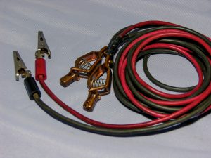
Twin alligator-clipped jumper leads.
Using twin alligator-clipped jumper leads (easily made by the DIYer; see the accompanying photo), attach one of the wires directly to the positive terminal at the water pump and string the test cable to the fuse box. It can route inside, outside, over cabinets, the sofa, etc., for now, as this is just a test. Connect the other end of that same wire to the output side of the fuse. The pump still does not run. Ah, but the other wire in the set of jumpers now can be used to test the negative side of the water pump circuit. Connect the other wire directly to the ground terminal at the pump, and the other end to the ground lug at the 12-volt distribution panel where the fuse is located. Aha! Now the pump runs fine. This verifies there was an open circuit in a section of wire on the ground side of the water pump circuit. The positive (+12) voltage was just fine.
Some people may now begin pulling drawers, disassembling cabinetry and walls etc., searching for that open section of the ground conductor. Don’t even bother looking for the actual open circuit. Simply bypass it by routing a new, properly sized wire to a good chassis ground connection. It is not necessary to run a new wire all the way to the grounded lug at the distribution panel if the problem is on the negative side of a DC circuit.
Of course, if the pump worked fine after jumping the hot side of the pump circuit, it would be necessary to route a new positive wire between the pump and the wall switch, or between the distribution panel and the wall switch, depending on where the break actually existed. But because the test jumper leads were used as a diagnostic tool to quickly determine that an open circuit existed on the negative ground side of the circuit, a new wire is easily routed. Just cut the old ground wire that contains the open section and leave it in place, wherever it may be.
Short circuits: DC shorts always result in a blown fuse or a tripped breaker. If the short cannot be located easily, simply run a new wire as outlined above. Shorts are caused by a number of circumstances, such as insulation rubbing through, chafed wires, poor connections, a staple or screw piercing the insulation, etc. The short almost always is in an inaccessible portion of the wall, ceiling, or undercarriage. RV service technicians are taught to search for the cause for a limited amount of time and then simply run a new conductor, bypassing the shorted section. The RV owner can do the same.
This systematic approach can be applied to any of the 12-volt-DC circuits. By not becoming overwhelmed at the thought of having to search for a cause, and by using tools correctly, it actually can be fun and challenging to troubleshoot 12-volt electrical problems. Well, sort of!
Final Thoughts
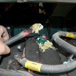
A corroded battery terminal connection.
In my seminars and videos about electricity, AC or DC, I mention three key words: clean, dry, and tight. Applying that advice to terminals, connections, multiplugs, distribution panels, ground connections — or wherever a conductor terminates or connects to another wire — will help eliminate or at least minimize the vast majority of DC electrical problems in RVs.
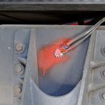
A proper negative ground connection.
You’ll also be able to maximize the use of your battery bank by understanding the components in the system, carefully upgrading as necessary, and ensuring that the batteries are charged and discharged properly.
Remember, RVing is more than a hobby; it’s a lifestyle!