
KEEPING ON THE SUNNY SIDE
As more RVers look to unplug from shore power, the installation of high-capacity solar systems is becoming more common. This article, first in a series, follows the upgrade process from start to finish.
By Steve Froese, F276276
As more RVers look to unplug from shore power, the installation of high-capacity solar systems is becoming more common. This article, first in a series, follows the upgrade process from start to finish.
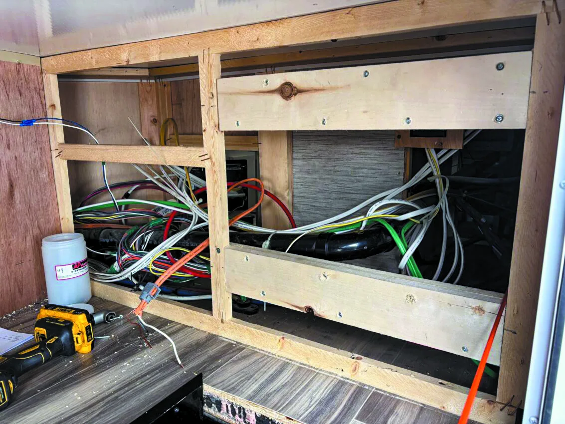
Paneling was removed to access the rear of the converter for wiring.
Recently, the company I work for had a customer request a major off-the-grid upgrade to his motorhome. In this series, I will describe the different equipment needed and its installation, which may be helpful to readers interested in similar upgrades to their units.
The customer wished to add 800 watts of solar power, which required installing a 2,000-watt inverter/charger; lithium batteries with 400 amp-hours of storage capacity; and a DC/DC charger. The latter is an extremely important but often overlooked component when adding lithium batteries to an electrical system. The need for this charger will be discussed in a corresponding article. In this installment, the installation of the inverter/charger will be covered.
Wood blocks were added to support the weight of the new inverter/charger
The RV in question was a late-model Class C motorhome. This is a common type of motorhome, so the upgrades were generic in scope. In fact, the procedures outlined in this series can be applied to any RV, with minor modifications, which will be pointed out along the way.
This motorhome was equipped with a standard converter. A full and correct inverter/charger upgrade is not difficult. But the term “correct” is used because some installers overlook an important step: disabling the existing converter charge module. The converter is responsible for providing 12-volt-DC power to the RV. Installation of the inverter/charger has a difficulty rating of three out of five. Be sure to follow the manufacturer’s installation instructions and adhere to all requirements.
The first step was to determine where to install the inverter/charger. It should be as close to the battery bank as possible, due to potential voltage loss in the cables. But it cannot be in the battery bay, where it would be exposed to outside elements, or anywhere that the inverter might become excessively hot or otherwise damaged.
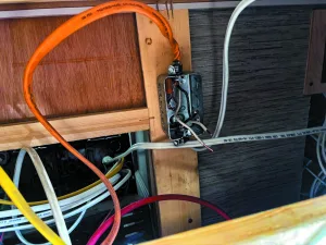
The battery wires were run from the inverter location to an electrical panel near the entry door.
In this case, the logical location was a large storage compartment. Although it was a bit of a distance from the batteries, it was the best option. This is common in many Class C motorhomes with minimal storage space. Consider the size and weight of the inverter/charger and the required ventilation space around the unit.
In this motorhome, the converter was located on the other side of the storage compartment. This was important, because the wiring needed to be routed to the batteries as well as the converter.
The inverter weighed around 40 pounds, so it also was important to ensure the installation location could support this weight. To gain access to the rear of the converter for wiring, as well as the cabinetry framing, it was necessary to remove several pieces of paneling at the install location. If a stapled panel must be removed, be careful to minimize damage to the panel and pull out all staples once it’s off. You will need to restaple the panel once the installation is completed, preferably with a pneumatic paneling stapler.
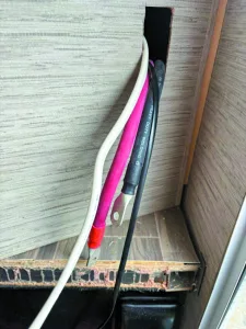
The wiring from the converter and battery was fed through the hole that was cut in the paneling before being attached to the inverter.
Once the panels were off, I installed extra wood bracing to the panel that the inverter would be attached to. Be sure to provide sufficient strength to support the inverter weight.
There was empty space from the area I was working in to the very end of the cabinetry, which ended at a panel beside the main door. This was a little unusual, but it made it easy to run the large 2/0-gauge battery wires from the inverter to the battery area, which was located under the entry step. Often, more extensive wire routing would be required, including removing additional panels or working under the unit, which adds complexity.
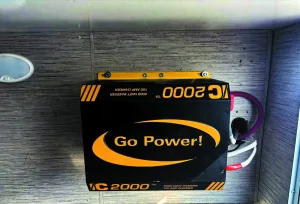
The installed inverter/charger.
I ran the large battery wires from the inverter location to the panel by the door. (A later step will involve getting the cables from inside the RV through the floor, then over to the batteries, which are mounted externally.) I also routed the remote control wire from the inverter location to the panel by the door.
The next step was to prepare the inverter’s AC wiring and remove the charge module from the converter. Identifying the main power line at the converter breaker panel is easy, since it is connected to the main 30-amp breaker. I disconnected the wire from the main breaker and traced it to the Romex wire coming from the transfer switch. Then I disconnected the main AC line in neutral and ground wires from their buss bars. This made it possible to completely remove the Romex wire from the converter. Since this is the main AC line coming into the RV from the transfer switch, which switches between shore power and generator power, this line would become the AC in line for the inverter. The AC out line from the inverter was wired back into the converter, directly replacing the original wire that was removed.
As mentioned earlier, it’s important to remove the “lower half” of the converter, the charge module. I disconnected the AC wires leading to the charge module. The black line will be connected to a breaker labeled “converter.” Similar to the main breaker wiring, the charge module will have the neutral and ground wires connected to buss bars. Disconnect these wires and feed them down to the module so it can be easily removed. Then disconnect the larger 12-volt red and white wires from the fuse block board, usually found on the right side. This might prove difficult and could involve loosening the fuse block from the converter case to allow the charge module wires to be released.
I then was able to remove the two screws holding the charge module and remove the module completely from the unit. This is a very important step that is often missed. The new inverter/charger will provide this functionality. If the charge module were left in place, problems could arise when the unit is put in “inverter” mode. With the charge module active, the inverter would provide AC power from the batteries while the charge module attempts to put power back into the batteries. Obviously, that would pose a major problem, so always remove the charge module, or at least fully disconnect it from the converter.
Before wiring the inverter, I cut a hole in the paneling. I passed the wires through the hole and connected the Romex wire that originally went into the converter into the AC in line for the inverter. Many inverter/chargers support 50-amp power, so pay close attention to the AC power wiring directions for the inverter.
Using a new piece of Romex, I connected the inverter out line back into the converter where I previously removed the original wiring.
I replaced the panel where I wanted to install the inverter. I added small crown staples to provide more strength. Then I installed the inverter on this panel, being sure to secure it to the wood backing I added.
I then connected the large 12-volt-DC wires to the inverter and plugged in the remote cable. The other wire needed was the chassis ground for the inverter. I ran this wire from the ground lug on the inverter into the converter and attached it to the ground buss.
I reinstalled the second panel and lined the wiring hole I had cut in the panel with split loom to improve the appearance. This completed the installation of the inverter/charger itself, but I still had to connect the battery wires and install the fuse and remote panel.
The fuse is normally provided with the inverter kit, but if not, you must purchase an appropriately sized fuse for the inverter and wiring gauge. Manufacturer’s instructions will provide guidance for doing this.
The fuse should be located as close to the batteries as possible. Removing the bottom drawers from the cabinetry below the oven and sink, I was able to gain access to a fairly large area of floor space. This is where I had previously fished the wires to. I installed the fuse on the floor in this area. Then I wired the positive wire from the inverter to one side of the fuse, and connected a second piece of wire to the other side of the fuse. Looking underneath the RV, I noted that there was sufficient space to drill holes from inside the cabinetry down through the floor to allow the required wires to run down from inside the unit to the outside. I passed the battery inverter wires through these holes directly to the batteries, accessible through an open frame.
Since the lithium batteries were not yet installed, I left the battery wires in that area for later hookup and testing.
Next was the installation of the remote panel. The ideal place for this was the end panel of the cabinet adjacent to the entry door. This is the panel behind which the wires were all previously fished, so it was an easy task. I simply used the provided template to cut a hole in the panel.
Pending testing of the inverter/charger, this concluded the installation of the inverter/charger.
In the next segment of this series, I will cover the lithium battery upgrade and subsequent testing of the inverter/charger.
RECALLS
Looking for the latest RV-related recall information? Visit FRVA.com for a list of the most recent recalls issued by RV and component manufacturers. Or, to search for recalls, investigations, and complaints by vehicle year, make, model, and VIN, visit nhtsa.gov/recallsnhtsa.gov/recalls. NHTSA’s Vehicle Safety Hotline is (888) 327-4236.
SEND YOUR TROUBLESHOOTING QUESTIONS to Steve Froese at techtalk@frva.com. The volume of correspondence may preclude personal replies. Not all responses will apply in every instance. Some situations may require a visual inspection and hands-on testing. If you choose to follow any procedures outlined in this column, first satisfy yourself that neither personal nor product safety will be jeopardized. If you feel uncomfortable about a procedure, stop and make an appointment with an RV service facility.